
Oscillator Parameters
To properly spec an oscillator, we need to establish several parameters. So we'll all be on the same page, I've outlined below the main ones.
[To the many of you who know more about this subject than I do, please forgive any oversimplification or bad examples!]
There are about five and one half specifications that define the performance of an oscillator in the frequency domain:
Accuracy
How close is the frequency or clock readout to an external reference (cesium frequency standard, or UTC time scale)? This is a single number specified as a ratio (e.g., parts per billion) or as an absolute (e.g., +/- 0.001 Hz, or +/- 10 nanoseconds).
Short Term Stability
How much does the oscillator's frequency wobble around during measurement intervals of interest? Short term stability is important for time interval measurements, where in effect it provides error bars around the measurement.
"Short term" doesn't have a specific cutoff, but it's usually thought of as measurement intervals of a day or less. Short term stability is stated at a specific interval by a statistic called Allan Deviation. The measurement interval is called "tau" and saying "tau=10 seconds" means each reading is taken ten seconds apart).
Long Term Stability
How constant is the oscillator's frequency over periods of days, weeks, or longer? Long term stability has two main components: drift, or aging, and flicker noise floor. Most oscillators exhibit drift, or aging -- a gradual change of rate over ong time periods. All crystal and rubidium oscillators drift; cesium beam standards do not. Long term stability is usually considered to include averaging times of a day or more. It is also stated as Allan Deviation, and where appropriate by an aging rate, such as "1x10e-10/day". The flicker noise floor is usually masked by drift, but is apparent in measurements of cesium beam frequency standards because they do not drift, but even then it only shows up at tau of several hundred thousand seconds.
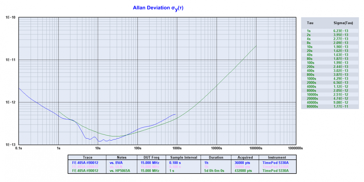
Allan Deviation
I mentioned Allan Deviation above. What is it? ADEV is a statistic similar to standard deviation but modified to better reflect the noise types exhibited by oscillators. It is dimensionless and is usually stated in the form "2.5 x 10e-8". Smaller is better! ADEV varies with measurement interval ("tau"), and is often plotted on a log-log graph with stability on the Y axis (lower is better) and tau on the X axis. From the slope of the curve, one can determine the noise processes at work n each segment of the graph.
Drift is apparent in ADEV graphs by a "bathtub" shaped curve where stability improves out to a few hundred or thousand seconds, flattens for a bit, and then goes up at longer averages as the drift becomes apparent. I've attached a sample ADEV graph so you can see what they look like.
Temperature Stability ("tempco")
Every resonator is a thermometer, and one of the challenges in crystal oscillator design is to prevent temperature changes from impacting the oscillation frequency. This is why we have TCXOs (temperature compensated crystal oscillator) and OCXOs (oven controlled crystal oscillator). Tempco is usually specified as parts per degree over a temperature range.
Phase Noise
How much unwanted phase modulation does the oscillator output carry? This is an important specification in RF systems because excessive phase noise increases the noise floor and impairs signal recovery by the receiver. On the transmit side, broadband phase noise can cause interference to nearby receivers.
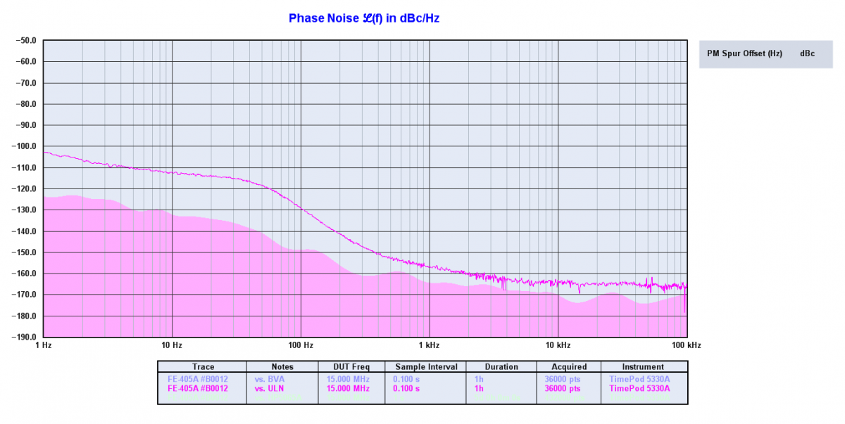
Phase noise is specified as dB down from the carrier (dBc) of the single sideband noise, normalized to 1 Hz bandwidth, at a given offset from the carrier -- e.g., 130 dBc/Hz @ 1 kHz offset. It is often plotted on a log-log graph. Various noise processes are shown by the slope of the PN plot. Most oscillators have a PN curve that drops at slope 1 to 2 from the carrier out to some point where the noise floor is reached and the PN remains constant from that offset outward. The closest offset usually measured is between 1 and 100 Hz, depending on the quality of the oscillator, and in the HF/VHF range region is usually measured out to 100 kHz or 1 MHz offset.Phase noise is really a short term stability at very short tau, and you can derive phase noise from an ADEV graph. PN is usually used for offsets of more than 1 Hz (which equals tau of 1 second), and ADEV for longer tau. I've also attached a sample phase noise graph.
Fun fact: phase noise increases by a minimum of 20log(N) with frequency multiplication. Double the frequency, increase the PN by 6 dB; multiply by 10 and add 20 dB to the noise. This is why phase noise is a major hassle in microwave systems.
Jitter
This is the 1/2 parameter mentioned above, because it is a different way of defining phase noise. It tries to reduce to one number the noise performance of an oscillator across a wide range of offset frequencies. Jitter is widely used in telecom clock specifications and is usually specified in femtoseconds or picoseconds of bit edge displacement. It's really another way of describing phase noise, and can be calculated from a phase noise plot. The gotcha is that you need to know the bandwidth over which the phase noise is integrated, and that's often not clearly stated in the data sheet.
Page Courtesy of John Ackermann N8UR